



 Orders
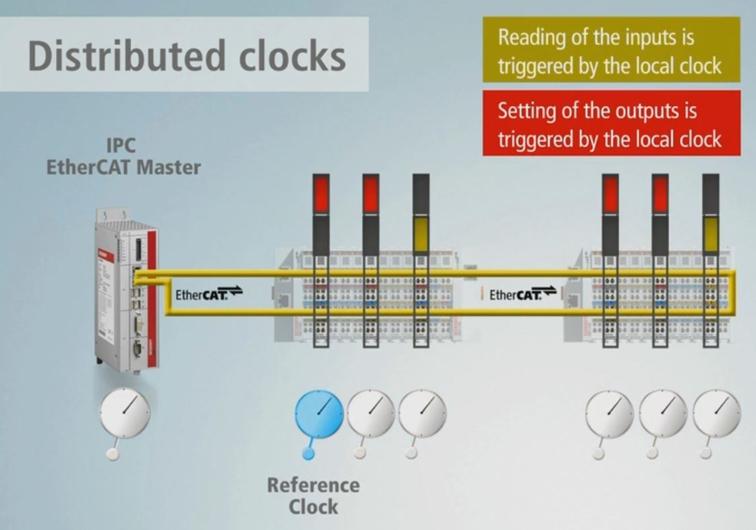
EtherCAT gives you fast cycle times. Distributed Clocks (DC) give you synchronized cycle times. The difference matters the moment you put a second axis on the bus.
Without synchronization, each drive acts on whatever frame it receives, subject to the variable propagation delay of the EtherCAT telegram traveling down the daisy-chain. Two drives at opposite ends of a ten-slave network can see the same command frame separated by tens of microseconds. For a single-axis system that is irrelevant. For a gantry, a delta robot, or any coordinated multi-axis machine, that skew accumulates into position error, vibration, and in the worst case a mechanical collision.
Distributed Clocks solve this at the hardware level. Every DC-capable slave runs an independent 64-bit hardware clock. All those clocks are synchronized to a single reference with sub-microsecond accuracy. Each slave then triggers its own local interrupt — the Sync0 signal — at a time derived from that shared reference. The drive samples its inputs and executes its control loop at the Sync0 edge, not when the telegram happens to arrive.
The Synchronization Problem in Multi-Axis Motion
Consider three servo drives controlling the X, Y, and Z axes of a Cartesian robot. The EtherCAT master sends one process data frame per cycle. That frame travels through slave 1 (X), then slave 2 (Y), then slave 3 (Z), each adding roughly 1–2 µs of forwarding delay per node.
Without DC:
Master sends frame at t=0
  Slave 1 (X) processes at t=1 µs
  Slave 2 (Y) processes at t=2 µs
  Slave 3 (Z) processes at t=3 µs
Each axis applies its torque command at a different moment in time. At 1 m/s tool speed, 3 µs of skew translates to 3 nm of position error between axes — negligible for most machines. But at high bandwidth with tightly coupled axes, the skew is not constant. Network load, IRQ jitter on the master, and cable length variation all make it stochastic. The drives are not synchronized — they are merely fast.
With DC, all three drives trigger their control loops from the same hardware edge regardless of when the EtherCAT frame arrives. The frame delivers the setpoints; the clock delivers the synchronization.
What Distributed Clocks Are
Every EtherCAT slave that supports DC contains a 64-bit hardware clock running at 1 GHz — 1 nanosecond resolution per tick. This clock is implemented in the slave's ESC (EtherCAT Slave Controller) ASIC, not in firmware or software. It runs independently on each node.
The DC register map is standardized across all ESC vendors:
| Register | Description | |---|---| | 0x0900 | System Time (64-bit, read) | | 0x0910 | System Time Offset (64-bit, write) | | 0x09A0 | Sync0 Cycle Time (32-bit, write) | | 0x09A8 | Sync0 Start Time (64-bit, write) | | 0x0981 | Sync0 enable bit |
During normal operation the clock increments every nanosecond. The master and all slaves negotiate a common time base, and each slave's offset register is adjusted so that System Time = Reference Time + propagation delay. After synchronization, all clocks read the same value to within a few hundred nanoseconds.
The Reference Clock
The first DC-capable slave in the EtherCAT ring becomes the reference clock. All other DC slaves synchronize their hardware clocks to this one node. The reference slave is not special hardware — it is simply the first one encountered during the initialization scan.
Master (software clock)
  |
  +-- Slave 1 [REFERENCE CLOCK]  <-- DC-capable, chosen as ref
       |
       +-- Slave 2 [sync to ref]
            |
            +-- Slave 3 [sync to ref]
                 |
                 +-- Slave 4 [no DC, free-run]
The master does not act as the DC reference. It reads the reference slave's clock and aligns its own cyclic frame transmission to that external hardware source. This inversion — the master following the slave rather than the slave following the master — is a common source of confusion but is fundamental to why DC achieves better synchronization than software-only approaches.
Propagation Delay Measurement
Before synchronization can work, the master must know how long it takes for a signal to travel between each consecutive pair of slaves. This is the propagation delay, and it is measured once during initialization using a hardware timestamp exchange.
The process works as follows. The master sends a frame with a timestamp written at departure. Each slave records its local clock value when the frame passes through, and again on the return path. The master reads all four timestamps back and calculates the cable delay between each adjacent node pair using the formula:
delay(n, n+1) = (T_forward_n+1 - T_forward_n) - (T_return_n - T_return_n+1)
                ─────────────────────────────────────────────────────────────
                                          2
These per-link delays are stored in each slave's propagation delay register (ec_slave[n].pdelay in SOEM). The slave then adds its own accumulated delay to the system time offset, so that when all clocks read t, they all mean the same physical moment at the reference slave.
Typical cable delays are 10–20 ns per meter of Cat5e. A ten-node network with 1-meter cables contributes roughly 100–200 ns of total accumulated delay — well below the Sync0 jitter floor.
The Sync0 Signal
Once the clocks are aligned, each DC slave generates a periodic hardware interrupt called Sync0. This signal is produced entirely inside the ESC ASIC — no firmware involved. The slave fires Sync0 at time:
T_sync0(n) = T_start + n * T_cycle
where T_start is a programmed start time in the future and T_cycle is the configured period. Both values are derived from the DC reference time, so all slaves fire their Sync0 edges at the same absolute moment on the synchronized time axis.
The drive's control loop firmware waits for this Sync0 edge, then samples encoders, runs the PID, and outputs torque — all triggered from the same hardware event regardless of network position.
Sync0 Cycle Time
The Sync0 period is written to register 0x09A0 and must match the master's cyclic loop period. Common values:
| Sync0 Period | Use Case | |---|---| | 250 µs | High-bandwidth servo (demanding) | | 500 µs | High-performance motion | | 1 ms | Standard motion control | | 2 ms | Slower processes, I/O |
The master's process data cycle and the Sync0 period do not have to be exactly equal, but they must be integer multiples of each other. Running a 1 ms EtherCAT cycle with a 500 µs Sync0 means the drive runs its inner control loop twice per EtherCAT frame, using interpolated setpoints for the intermediate cycle.
Enabling DC in SOEM
SOEM handles the full DC initialization sequence through a single call placed after ec_config_map() and before transitioning to OP state:
#include "ethercat.h"

int main(void) {
    ec_init("eth0");
    ec_config(FALSE, &IOmap);

    // Map PDOs
    ec_config_map(&IOmap);

    // Enable Distributed Clocks
    // - Detects DC-capable slaves
    // - Measures propagation delays (pdelay)
    // - Sets reference clock to first DC slave
    // - Programs Sync0 start time and cycle time on all DC slaves
    ec_configdc();

    // Transition to OP
    ec_statecheck(0, EC_STATE_SAFE_OP, EC_TIMEOUTSTATE * 4);
    ec_writestate(0);
    ec_statecheck(0, EC_STATE_OPERATIONAL, EC_TIMEOUTSTATE * 4);

    // Cyclic loop follows...
}
ec_configdc() performs the delay measurement, programs the system time offsets, and sets Sync0CycleTime to match the cycle period you configured when calling ec_config(). You do not need to write any DC registers manually unless you need a non-standard Sync0 multiplier.
After the call, verify that DC was activated:
for (int i = 1; i <= ec_slavecount; i++) {
    printf("Slave %d: DCactive=%d  pdelay=%d ns\n",
           i,
           ec_slave[i].DCactive,
           ec_slave[i].pdelay);
}
A DCactive value of 1 means the slave acknowledged DC and is generating Sync0. A value of 0 means the slave either does not support DC or was not reached during the measurement pass.
The Master's Role: Aligning to the DC Reference
Enabling DC on the slaves is half the problem. The master's cyclic loop must also be aligned to the DC reference clock, otherwise the process data frame arrives at a random phase relative to Sync0 and the drive has to buffer or interpolate setpoints.
The standard approach on Linux with PREEMPT-RT uses CLOCK_MONOTONIC and clock_nanosleep to align the wakeup to the DC reference time:
#include <time.h>

#define CYCLE_NS  1000000LL  // 1 ms in nanoseconds

int64_t ec_sync(int64_t reftime, int64_t cycletime, int64_t *integral)
{
    int64_t delta = (reftime % cycletime) - (cycletime / 2);
    if (delta > (cycletime / 2))  delta -= cycletime;
    if (delta < -(cycletime / 2)) delta += cycletime;
    *integral += delta;
    return -(delta / 100) - (*integral / 10000);
}

void cyclic_task(void) {
    struct timespec ts;
    int64_t toff = 0, integral = 0;

    clock_gettime(CLOCK_MONOTONIC, &ts);
    // Align start to next cycle boundary
    ts.tv_nsec = (ts.tv_nsec / CYCLE_NS + 1) * CYCLE_NS;
    if (ts.tv_nsec >= 1000000000LL) {
        ts.tv_nsec -= 1000000000LL;
        ts.tv_sec++;
    }

    while (1) {
        clock_nanosleep(CLOCK_MONOTONIC, TIMER_ABSTIME, &ts, NULL);

        // Read reference clock from DC reference slave
        int64_t reftime = ec_DCtime;

        // Calculate phase correction
        toff = ec_sync(reftime, CYCLE_NS, &integral);

        // Send and receive process data
        ec_send_processdata();
        ec_receive_processdata(EC_TIMEOUTRET);

        // Advance wakeup time with phase correction applied
        ts.tv_nsec += CYCLE_NS + toff;
        while (ts.tv_nsec >= 1000000000LL) {
            ts.tv_nsec -= 1000000000LL;
            ts.tv_sec++;
        }
    }
}
The ec_sync() function is a proportional-integral controller that drives the master's frame transmission phase toward the DC reference. ec_DCtime is updated by SOEM after each ec_receive_processdata() call and contains the current reference slave system time. Over several hundred cycles the master's wakeup drifts into alignment, typically settling within 1–5 µs of the DC reference edge.
Jitter Budget: Free-Run vs. DC
The practical impact of Distributed Clocks on synchronization quality:
Free-run (no DC):
  Master wakeup jitter          ±200 µs  (unpatched kernel)
  Master wakeup jitter          ±10 µs   (PREEMPT-RT)
  Slave-to-slave skew           ±500 µs  (accumulates with bus load)

With DC enabled (PREEMPT-RT master):
  Reference clock accuracy      ±100 ns  (hardware)
  Slave-to-slave Sync0 skew     <1 µs    (after convergence)
  Master frame phase error      1–5 µs   (PI controller, settled)
The improvement is three orders of magnitude on slave-to-slave skew. For a 1 ms cycle running at 1 kHz, free-run jitter of ±500 µs means a slave might see two consecutive frames 0.5 ms apart or 1.5 ms apart. With DC, every slave acts at exactly the same moment to within a microsecond.
When DC Matters — and When It Does Not
DC is essential when:
- Two or more axes are mechanically coupled (gantry, delta robot, SCARA)
- Torque or velocity feed-forward is synchronized across axes
- Electronic gearing or CAM profiles link multiple drives
- The machine has tight path-following requirements at high speed
DC is not necessary when:
- You have a single axis with no coordination requirements
- Cycle times are 5 ms or slower with loose position tolerances
- The slaves are I/O modules, not servo drives
- The application is monitoring or data acquisition, not actuation
Adding DC to a single-axis system does no harm and costs nothing at runtime, but the synchronization infrastructure is doing no useful work if there is nothing to synchronize with.
Checking DC Status
After initialization, SOEM exposes DC state through the slave structure:
// Check per-slave DC status
for (int i = 1; i <= ec_slavecount; i++) {
    printf("Slave %2d | Name: %-20s | DCactive: %d | pdelay: %6d ns\n",
           i,
           ec_slave[i].name,
           ec_slave[i].DCactive,
           ec_slave[i].pdelay);
}

// Read current DC reference time
printf("DC reference time: %lld ns\n", (long long)ec_DCtime);
You can also query the slave's current Sync0 offset error over EtherCAT using register 0x092C (System Time Difference), which shows how far the slave's local clock currently deviates from the reference. Values above a few hundred nanoseconds after convergence indicate a wiring problem or a slave with a drifting oscillator.
Common DC Problems
No DC-capable slaves detected. ec_configdc() returns without setting any DCactive flags. Cause: the slaves in your network do not support DC, or you are using EtherCAT-compatible hardware that implements only the basic slave protocol without the DC extension. Check the slave's ESI file for <Dc> entries.
Time offset drift over hours. The reference slave's oscillator has a non-zero frequency error relative to other slaves. DC includes a continuous drift compensation mechanism, but if the reference slave has a poor oscillator, accumulated error can reach tens of nanoseconds per second. Mitigation: choose a reference slave with a TCXO-grade oscillator, or configure the sync manager to use an external clock reference if the ESC supports it.
Wrong Sync0 period. The slave's Sync0 is programmed to a different period than the master's cyclic loop. Symptom: the drive faults with a synchronization error after a few seconds. Cause: ec_configdc() reads the cycle time from the ec_slave[0].DCtime field, which is set by the ec_config() call. If you change the cycle time after calling ec_configdc(), the slaves are not reprogrammed. Always call ec_configdc() after finalizing the cycle time.
Master phase never converges. The PI controller in ec_sync() keeps oscillating. Cause: the gains are too aggressive for the kernel's timer resolution, or the PREEMPT-RT patch is not active. Run uname -v | grep PREEMPT_RT to confirm the RT kernel is booted. Also verify that the cyclic thread is running at SCHED_FIFO priority 80 or higher.
Multi-Axis EtherCAT Motion — Synchronized to Microseconds
Lichi Robotics implements EtherCAT Distributed Clocks in production systems across India — ensuring sub-microsecond synchronization for multi-axis robots, CNC machines, and automated assembly lines.
👉 Explore EtherCAT Solutions →
WhatsApp Us — free demo with full setup support.