



 Orders
CiA 402 Drive Profile Explained: State Machine, Modes, and EtherCAT Integration
Every EtherCAT servo drive you will encounter in industrial robotics — whether it is a Yaskawa Sigma-7, Siemens SINAMICS, Delta ASDA-A3, or Panasonic MINAS A6 — speaks the same fundamental language for commissioning and motion commands. That language is CiA 402.
What Is CiA 402?
CiA 402 is the CANopen device profile for drives and motion control, defined by CAN in Automation (CiA) and standardized as IEC 61800-7-201. It specifies a uniform object dictionary, a state machine, and a set of operation modes that any conformant servo or stepper drive must implement.
When EtherCAT was adopted as the physical layer for high-speed motion control, the CiA 402 object dictionary was carried over almost unchanged. The EtherCAT variant is formally called IEC 61800-7-204 (CoE — CANopen over EtherCAT), but the object indices, bit definitions, and state machine are identical to what you find in pure CANopen systems. This is why a single software stack can control drives from a dozen different manufacturers: the profile is the contract.
The implications for system integrators are significant. Learn CiA 402 once, and you can bring up any compliant drive over EtherCAT without reading a vendor-specific state machine diagram. Vendor manuals still matter for tuning, I/O configuration, and proprietary objects — but the commissioning sequence is standardized.
The CiA 402 State Machine
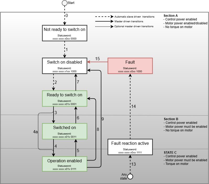
The drive state machine is the gatekeeper between power-on and motion. Before a drive will accept position, velocity, or torque commands, it must pass through a defined sequence of states. Attempting to skip states or send commands in the wrong state results in either an error or silent inaction.
The eight states and their transitions are:
                         ┌──────────────────────┐
                         │  Not Ready to Switch On│  (internal self-test, power-on)
                         └──────────┬───────────┘
                                    │ automatic
                                    ▼
                         ┌──────────────────────┐
                    ┌───▶│  Switch On Disabled   │◀──── Fault Reset / Disable Voltage
                    │    └──────────┬────────────┘
                    │               │ Shutdown (CW=0x0006)
                    │               ▼
                    │    ┌──────────────────────┐
                    │    │  Ready to Switch On   │
                    │    └──────────┬────────────┘
                    │               │ Switch On (CW=0x0007)
                    │               ▼
                    │    ┌──────────────────────┐
                    │    │      Switched On      │
                    │    └──────────┬────────────┘
                    │               │ Enable Operation (CW=0x000F)
                    │               ▼
              Fault │    ┌──────────────────────┐
           Reaction │◀───│  Operation Enabled    │◀──▶ Quick Stop Active
                    │    └──────────────────────┘
                    │
                    ▼
           ┌─────────────────────┐        ┌─────────────────────┐
           │  Fault Reaction     │───────▶│        Fault         │
           │      Active         │        └─────────────────────┘
           └─────────────────────┘
Not Ready to Switch On — the drive is initializing. No controlword commands are accepted. The drive exits this state automatically once self-test passes.
Switch On Disabled — power stage is disabled, no DC bus power to the motor. This is the first stable state reachable after power-on. From here, all valid commissioning paths begin.
Ready to Switch On — the drive has acknowledged the Shutdown command and is ready to energize the power stage. Still no torque on the shaft.
Switched On — the power stage is active and the drive is holding position (typically with the brake released), but the control loop is not yet executing motion commands.
Operation Enabled — the control loop is running. The drive will now respond to target position, velocity, or torque depending on the configured operation mode. This is the state required for all motion.
Quick Stop Active — triggered by bit 2 of the controlword being cleared. The drive executes a fast controlled stop (deceleration rate set by object 0x6085). Typically transitions back to Switch On Disabled after completion.
Fault Reaction Active — a fault was detected while in Operation Enabled. The drive performs a fault reaction (coast stop or quick stop depending on configuration) before latching into Fault.
Fault — the drive has latched a fault. Motion is impossible. The fault must be identified, the cause corrected, and a Fault Reset command issued to return to Switch On Disabled.
Controlword (Object 0x6040)
The controlword is a 16-bit PDO-mapped output from the master to the drive. The lower byte drives state transitions; specific bits control motion behavior.
| Bit | Name | Function | |-----|------|----------| | 0 | Switch On | Part of state transition command | | 1 | Enable Voltage | Part of state transition command | | 2 | Quick Stop | 0 = trigger quick stop; 1 = normal | | 3 | Enable Operation | Part of state transition command | | 4 | Operation Mode Specific | In PP mode: new set-point trigger | | 5 | Operation Mode Specific | In PP mode: change set immediately | | 6 | Operation Mode Specific | Reserved / mode-specific | | 7 | Fault Reset | Rising edge resets fault | | 8 | Halt | 1 = halt motion (mode dependent) |
The key controlword values for state transitions are:
Shutdown:          0x0006   (bits: EN_V=1, QS=1, SO=0)
Switch On:         0x0007   (bits: EN_V=1, QS=1, SO=1)
Enable Operation:  0x000F   (bits: EN_V=1, QS=1, SO=1, EO=1)
Disable Voltage:   0x0000
Quick Stop:        0x0002   (bit 2 cleared)
Fault Reset:       0x0080   (bit 7 high, then return to 0x0006)
Statusword (Object 0x6041)
The statusword is a 16-bit PDO-mapped input from the drive to the master. The master reads this to determine the current state and detect errors.
| Bit | Name | Meaning when set | |-----|------|-----------------| | 0 | Ready to Switch On | Drive passed internal checks | | 1 | Switched On | Power stage active | | 2 | Operation Enabled | Control loop running | | 3 | Fault | Fault latched | | 4 | Voltage Enabled | DC bus voltage present | | 5 | Quick Stop | 0 = quick stop active | | 6 | Switch On Disabled | Drive in SOD state | | 7 | Warning | Non-fatal warning present | | 10 | Target Reached | Drive reached commanded target | | 12 | Operation Mode Specific | Mode-specific status | | 15 | Homing Attained | Home position found (mode 6) |
State decoding from statusword (mask the relevant bits):
SOD state:    (sw & 0x4F) == 0x40
RtSO state:   (sw & 0x6F) == 0x21
Switched On:  (sw & 0x6F) == 0x23
Op Enabled:   (sw & 0x6F) == 0x27
Fault:        (sw & 0x4F) == 0x08
Quick Stop:   (sw & 0x6F) == 0x07
Bringing a Drive to Operation Enabled with SOEM
SOEM (Simple Open EtherCAT Master) is the most widely used open-source EtherCAT master library. The following sequence uses SDO writes during pre-operational phase to commission the drive, then transitions to operational.
#include "ethercat.h"

#define CONTROLWORD_IDX  0x6040
#define STATUSWORD_IDX   0x6041
#define OPMODE_IDX       0x6060

int slave = 1; /* SOEM slave index, 1-based */

/* Step 1: Set operation mode before enabling (CSP = 8) */
uint8_t opmode = 8;
ec_SDOwrite(slave, OPMODE_IDX, 0x00, FALSE, sizeof(opmode), &opmode, EC_TIMEOUTRXM);

/* Step 2: Shutdown command — transition to Ready to Switch On */
uint16_t cw = 0x0006;
ec_SDOwrite(slave, CONTROLWORD_IDX, 0x00, FALSE, sizeof(cw), &cw, EC_TIMEOUTRXM);
osal_usleep(20000); /* 20 ms settle */

/* Step 3: Switch On — transition to Switched On */
cw = 0x0007;
ec_SDOwrite(slave, CONTROLWORD_IDX, 0x00, FALSE, sizeof(cw), &cw, EC_TIMEOUTRXM);
osal_usleep(20000);

/* Step 4: Enable Operation — transition to Operation Enabled */
cw = 0x000F;
ec_SDOwrite(slave, CONTROLWORD_IDX, 0x00, FALSE, sizeof(cw), &cw, EC_TIMEOUTRXM);
osal_usleep(20000);

/* Step 5: Verify state via statusword */
uint16_t sw = 0;
int size = sizeof(sw);
ec_SDOread(slave, STATUSWORD_IDX, 0x00, FALSE, &size, &sw, EC_TIMEOUTRXM);
if ((sw & 0x6F) == 0x27) {
    printf("Drive is in Operation Enabled state\n");
} else {
    printf("State error: statusword = 0x%04X\n", sw);
}
In a real system, state verification should use a polling loop with a timeout rather than fixed delays. Many drives also require that the PDO mapping is configured and the master has entered OPERATIONAL state (ec_state = EC_STATE_OPERATIONAL) before controlword writes via PDO take effect. The SDO path above works in PRE-OP and SAFE-OP for initial commissioning.
Operation Modes (Object 0x6060 / 0x6061)
Object 0x6060 is the Modes of Operation register — written by the master to select the control mode. Object 0x6061 is Modes of Operation Display — read back from the drive to confirm the active mode. Never command motion until 0x6061 confirms the mode has been accepted.
Cyclic Synchronous Position (CSP, Mode 8)
The most common mode for EtherCAT multi-axis systems. The master sends a target position (0x607A) every EtherCAT cycle (typically 1 ms or 500 µs). The drive's internal position controller closes the loop locally, so network jitter does not degrade position accuracy. The master is responsible for trajectory generation — interpolating waypoints into per-cycle position targets.
Cyclic Synchronous Velocity (CSV, Mode 9)
The master sends a target velocity (0x60FF) each cycle. The drive executes its internal velocity controller. Useful when the master implements velocity-level trajectory planning, or for applications like conveyors where position tracking is not the primary objective.
Cyclic Synchronous Torque (CST, Mode 10)
The master sends a target torque (0x6071) each cycle, and the drive's current controller executes it. Used in force control, impedance control, and torque-based manipulation. The master must implement full outer-loop control (position or velocity) and output torque commands at cycle rate.
Profile Position (PP, Mode 1)
The master specifies a target position, velocity, acceleration, and deceleration via SDO or PDO, then triggers a move by toggling bit 4 of the controlword. The drive's internal trajectory generator produces the motion profile. Useful for point-to-point moves where the master does not need to provide per-cycle waypoints. Less common in synchronized multi-axis EtherCAT systems but adequate for single-axis positioning.
Profile Velocity (PV, Mode 3)
Similar to PP but the master specifies a target velocity and the drive ramps to it using its internal profile generator. Suited to applications requiring smooth speed control without per-cycle master intervention.
Commanding Motion in CSP Mode
With the drive in Operation Enabled and mode confirmed as CSP (0x6061 reads 8), motion is commanded by writing the target position and keeping the controlword at 0x000F. In a PDO-based cyclic loop:
#define TARGET_POS_IDX  0x607A
#define ACTUAL_POS_IDX  0x6064
#define ACTUAL_VEL_IDX  0x606C
#define ACTUAL_TRQ_IDX  0x6077

/* Write target position (user units, drive dependent — usually encoder counts) */
int32_t target = 100000; /* 100000 counts */
ec_SDOwrite(slave, TARGET_POS_IDX, 0x00, FALSE, sizeof(target), &target, EC_TIMEOUTRXM);

/* In cyclic PDO loop, target position is mapped to the output PDO */
/* and the controlword remains 0x000F (Operation Enabled, no halt) */
Reading Feedback Objects
The three primary feedback objects available in all CSP/CSV/CST modes:
| Object | Name | Type | Typical Unit | |--------|------|------|-------------| | 0x6064 | Position Actual Value | INT32 | Encoder counts | | 0x606C | Velocity Actual Value | INT32 | Counts/second or 0.1 rpm | | 0x6077 | Torque Actual Value | INT16 | 0.1% of rated torque |
These are mapped to input PDOs in a cyclic system. In SOEM, after ec_receive_processdata(), they are read directly from the slave's IOmap memory rather than via SDO, giving deterministic low-latency feedback.
Homing Mode (Mode 6)
Before absolute positioning is meaningful, many systems require a homing sequence to establish a known reference position. CiA 402 homing mode (0x6060 = 6) defines 35 homing methods covering combinations of limit switches, index pulses, and torque-based hard stops.
Key homing objects:
- 0x6098 — Homing Method (1–35 + vendor-specific negative values)
- 0x6099 — Homing Speeds (sub-index 1: search speed, sub-index 2: zero speed)
- 0x609A — Homing Acceleration
- 0x607C — Home Offset (applied to position after home found)
The homing sequence is initiated by writing mode 6, then triggering the start via bit 4 of the controlword. Bit 15 of the statusword (Homing Attained) goes high when the sequence completes successfully. Bit 13 (Homing Error) indicates failure.
In EtherCAT multi-axis systems, homing is typically performed axis-by-axis in SAFE-OP before transitioning to full cyclic motion in OPERATIONAL state.
CiA 402 Integration Done For You
Lichi Robotics implements complete CiA 402 EtherCAT servo commissioning — state machine management, mode configuration, and cyclic motion control — for any compatible drive.
WhatsApp Us — free demo with full technical support.